
This was a fun multi-faceted project that uses off-the-shelf components. It encompasses electronic component design, programming, mechanical design and some simple plumbing. Most components are readily available from the usual sources. This project does not require extensive specialized skills as it consists of soldering of electronics components, measuring and drilling.
Other than schematic page and bill of materials, there are no other design files associated with this project.
Introduction
In June 2022, I moved my mother and I from Southeast Florida to Northeast Alabama. It was a bit stressful as there was a full 3 bedroom house and two small sheds of “stuff” to pack and dealing with the pricey movers and their games to get more $$$ out of you. Not to mention dealing with the sub-contractors for repair work and such in the new location. We have great neighbors that check in on us from time to time. After all, we are much happier in the rural setting and don’t miss Southeast Florida. Well, except for the bikinis and thong bathing suits of the Florida beaches!
In the summer of 2023, we visited the local Farmer’s Market run by the Mennonites in a little town called Section. That year they started to sell junior plants for home gardens; fruits, vegetables and herbs. They were about 1/3 the price as those offered by the big box stores. At that time, we only grew tomatoes in two small planters because I was not willing to spend the $$$ to dig up a plot of land for a larger garden nor spend the time maintaining it as my other neighbors do. The planters were adequate but I could see that next year’s crop was going to need a larger container.

This summer (2024), in addition to tomatoes, we decided to grow bell peppers and green beans but I wanted larger pots to grow them in. Our neighbor across the street raises his garden plot every year. He and his wife spend lots of time jarring and canning their yield at the end of the season. He suggested I acquire a livestock “Mineral Lick Tub” to use as a large planter. Another neighbor, who has 35 acres of land behind us that he uses as a hay field, raises cattle (he goes through 500 rolls of hay a year!). I asked him one day if he had any of these “Mineral Lick Tubs”, to which he replied “I’ll round you up a few”. A week later, he brought me four (4) of them. These Mineral Lick Tubs are made of black plastic and have tight fitting lids. They are 21″ in diameter and 19″ in height. I guesstimate they hold about 25 gallons of water. Perfect for our application!
On to the design of the Rain Barrel Drip Irrigation System…
Design Goals
My intention for this project was to design an automatic drip irrigation system that would provide me with:
- Easy to source components; electronic and mechanical.
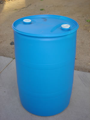
- Use a 55 gallon plastic barrel as the water reservoir (with removable lid for cleaning/repairs).
- Use rain water captured from a gutter downspout.
- Use an inexpensive pump for the water delivery system.
- A means to interface with and program the controller via intranet (LAN) using the popular ESP8266 WiFi module.
- Use the popular TASMOTA project as the automation firmware for the ESP8266.
- Optional – send MQTT IoT status messages to an MQTT Broker on the LAN.
- Use a solid-state relay to control the pump.
- Use a float sensor to disable the pump if the water level is too low.
- Enclose all electronics in a waterproof enclosure attached to the barrel.
- Provide a means to filter the incoming water from the gutter downspout.
- Provide a means to allow water to overflow should the barrel get filled to capacity during a storm.
- Provide a means to either drain the barrel, fill a bucket or attach a standard garden hose using a spigot.
- A means to determine the water level in the barrel.
- Long power cord to reach a nearby power outlet.
- Self-contained autonomous system that can be drained and moved inside during the winter months to protect the components from freezing.
With the aforementioned design goals in mind, I set out to research the basic electrical and mechanical interfacing between the various components.
There are many web sites that describe rain barrel projects; both simple (no automation) and automated. Some of the web sites I referenced are:
- https://morningchores.com/diy-rain-barrel/
- https://www.itsoverflowing.com/diy-rain-barrel-ideas/
- https://www.familyhandyman.com/project/how-to-build-a-rain-barrel/
- https://www.primalsurvivor.net/diy-rain-barrel/
- https://www.hackster.io/news/upgrading-an-irrigation-controller-with-esp8266-tasmota-and-home-assistant-e214c1821005
- https://docodethatmatters.com/automate-sprinkler-with-tasmota/
After researching many other projects, I decided upon a method of design for my own Rain Barrel Drip Irrigation System. I’ve not seen any other online projects quite like my own, so I’m posting it for others to reference.
Component Selection

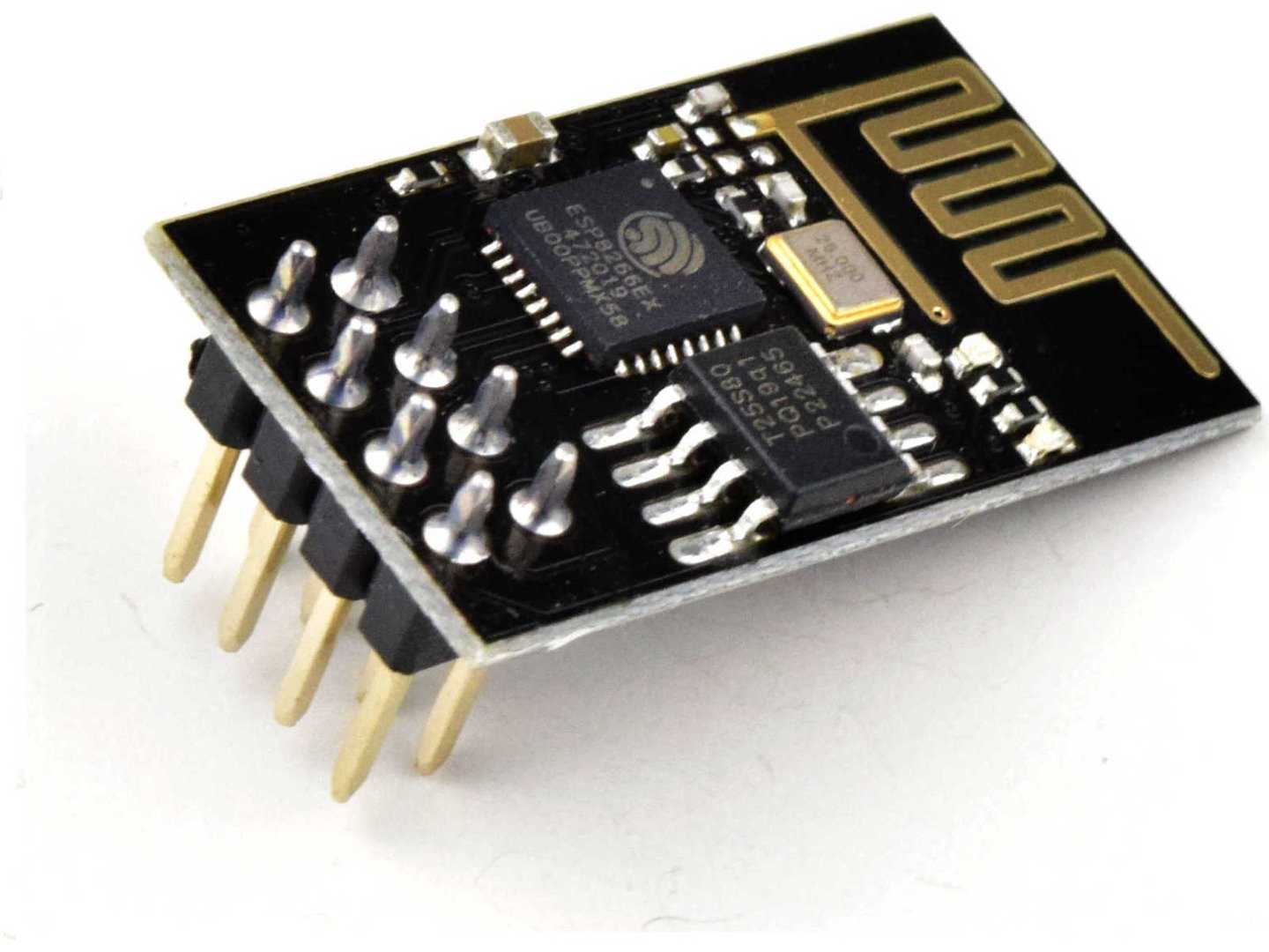
Controller: The heart of this design is the ESP8266 low-cost WiFi Integrated Circuit (IC), thus the rest of the electronics for the system is built around it. The ESP-01 PCB module is a low-cost WiFi module that costs around US$1.25 from the usual Chinese suppliers. Its a small board, measuring ~1″ x 0.6″. The ESP-01 PCB module has 8 pins.

Water Pump: The second most important component of the irrigation system is the pump. There are many styles and cost ranges. AMAZON has an assortment of them. Every year there is “the world’s longest yard sale” that runs through our area. It spans 6 states and 690 miles. It’s really just a series of yard sales that run a predetermined route. In August 2023, I ran across a new LITTLE GIANT 2E-NYS series submersible parts washer pump in its original box. Its an impeller pump that is used to recirculate liquids at 100 gallons per hour up a vertical distance of 9 feet. It will produce little pressure, only about 5.1 psi per the manufacturer’s specifications. The run current is ~ 1.5 amps. I acquired the pump for US$10, whereas new, it would have cost me US$225!
Note that as an alternative, I found several decent priced submersible pumps on AMAZON that would fill the pump requirement. This one at US$20 is probably better suited for the job than the pump I am using but since I’m not looking for water pressure but water flow and the pump I obtained was a lucky find for $10 and there was no reason to add more cost to the project.

Water Reservoir: A standard 55 gallon food grade plastic drum was selected because my neighbor down the road has a small stock of these drums, which cost me US$10 to purchase. I chose “food-grade” because these barrels are used to transport many types of products, including “acids”. Some residue from their previous function may remain on the walls of the drum, which may leak into the water supply and damage, poison and/or kill the plants. The two I selected were for transporting Polysorbate-80, which is used as an emulsifier in foods, so safe for plants(?). Note that the industry is getting away from these round drums in favor of the rectangular Intermediate Bulk Container (IBC) Tanks because their shape makes them easier to handle and store.

Rain gutter downspout diverter: I looked at several methods for this task. AMAZON had an assortment of them as well. Some were pricey and seemed over-complicated. I finally settled on the single piece “EARTHMINDED FlexiFit Diverter Upgrade for 3 x 4 Inch Rectangular Downspouts“. The AMAZON price was ~US$16. The installation was simple and easy using a 2-1/8″ hole saw and the provided stainless-steel self-tapping screws.

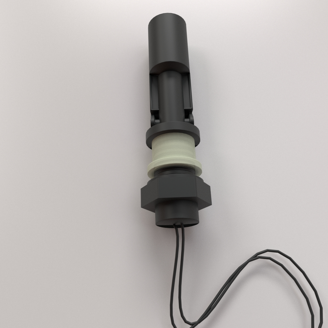
Water Level Float Switch: There are many types and cost ranges for float switches. They come in plastic or steel and vertical or horizontal mount varieties. I chose the plastic horizontal mount style because I was going to position it just above the input water line to the pump. The internal switching mechanism is a reed switch, which is low-current, so it can’t be used for directly switching the 120 VAC to the pump. I purchased 6 switches from an AMAZON vendor. The cost per switch was ~US$2.00 each.

Solid-state Relay: rather than design my own, which would require a heat sink and electrical isolation, I decided to use a solid-state relay (SSR) module. I had one of these devices left over from the SMT Reflow Oven project. However, I chose to purchase two of them from an AMAZON seller. The device is a HILETGO SSR-25DA Solid State Relay Module, which had a unit cost of ~US$6.50. These devices will handle 25 amps of AC current at 250 VAC and provide optical isolation from the controller’s circuitry.

Controller Software: In a prior project having to do with temperature/humidity/barometric pressure readings using an ESP-01 module, I came across a project called TASMOTA. TASMOTA is an open source firmware for ESP devices, which provides total local control of an ESP device using MQTT, Web UI, HTTP or serial communications. It has 16 timers, 3 rules and the ability to execute scripts. Since I’m using an ESP8266 and TASMOTA is designed to run on an ESP8266 then TASMOTA is the best fit for this project.

Power Supply: The ESP8266/ESP-01 PCB module requires a power supply voltage of 2.5 to 3.6 volts DC at a peak current of ~250ma during power-up and when the RF radio is transmitting. I have dozens of “wall-wart” style power supplies at various voltages and many AS1117 3.3V voltage regulators in my stock. With a proper heat-sink, the AS1117 can deliver up to 800ma of current, so I chose it for this project and gutted the power transformer from a 9 VDC @ 500ma “wall-wart” power supply.

Waterproof enclosure: In order to meet the design requirement of “self-contained autonomous”, which means the controller will be outside in various weather conditions and it needs to mount on the side of the rain barrel. Thus, I needed to use a waterproof enclosure that was small enough to attach to the side of the barrel (it’s a curved surface) but large enough to hold the main PCB, the SSR, the power transformer, the terminal blocks to connect the wiring to, and allow 3 wire inlets. I settled on an AMAZON seller’s offering of a 5.9″ x 5.9″ x 3.5″IP67 Waterproof enclosure. It comes with mounting hardware, an internal mounting base plate, 2 @ 1/2″ NPT cable glands and 2 @ 3/8″ NPT cable glands.
Electronic Circuitry Design

ESP8266 Controller: The ESP8266 is the heart of the system. The part is called a “System a on Chip“. From the data sheet, it contains:
- An 802.11 b/g/n WiFi Transceiver
- Integrated low power 32-bit MCU
- Integrated 10-bit ADC
- Integrated TCP/IP protocol stack
- Integrated TR switch, balun, LNA, power amplifier and matching network
- Integrated PLL, regulators, and power management units
- Supports antenna diversity
- WiFi 2.4 GHz, support WPA/WPA2
- Support Smart Link Function for both Android and iOS devices
- SDIO 2.0, (H) SPI, UART, I2C, I2S, IR Remote Control, PWM, GPIO
- Deep sleep power <10uA, Power down leakage current < 5uA
- Wake up and transmit packets in < 2ms
- Standby power consumption of < 1.0mW (DTIM3)
- +20 dBm output power in 802.11b mode
- Operating temperature range -40C ~ 125C
- FCC, CE, TELEC, WiFi Alliance, and SRRC certified
The ESP8266 comes on a small module, the ESP-01. The ESP-01 PCB module has 8 pins; power and ground, RESET, ENABLE, TX and RX for firmware programming and two I/O pins. For this application, I’ll need only a single I/O pin to drive the control input of the solid-state relay along with power and a means to reset the device in case it get glitched somehow. I’ll write more about the TASMOTA automation firmware that runs on the ESP8266 further along in this article.
Power Supply: I originally was thinking to use an AC to DC converter module but I didn’t have any available in my personal stock. The solution, of course, was to design my own. I knew I needed to supply a high enough voltage to the AS1117 voltage regulator to stay above its drop-out voltage of ~1.25 volts and below it’s maximum input voltage of 20 volts. Since I had gutted the power transformer from a “wall-wart” power supply, I would need to rectify the AC voltage from the transformer’s secondary winding to DC voltage using a standard silicon bridge rectifier. Keeping in mind that there is an inherent forward voltage drop across the bridge rectifier of ~1.2 volts. Adding the maximum voltage regulator drop-out voltage and the forward voltage drop of the bridge rectifier meant I had to supply at least 6 volts DC ( (3.3V + 1.25V) + 1.2V ) to the voltage regulator. Supplying a higher voltage would only result in the voltage regulator dissipating more heat.
The final design resulted in using the transformer from a 9 VDC/500 ma “wall-wart” power supply. The rectified voltage under load was about 8 volts to the voltage regulator input. The AS1117 is packaged in a SOT-89 surface mount package. The supplier’s datasheet recommends using the copper on the PCB as a heat-sink. Since I wasn’t planning to have this board produced at a PCB fabrication supplier, I had to create my own heat-sink and SMT land pattern out of copper foil. As shown below, an X-Acto razor knife worked well for this purpose.

Note: If one has a regulated 3.3 volt power supply capable of supplying >=300 ma, it can be substituted for the power supply I describe above.
Solid-state Relay Driver: In designing the ESP8266 to solid-state relay (SSR) interface, I had to keep in mind the power supply voltage of the ESP8266 and the minimum drive voltage/current of the SSR, which is 3 volts DC @ 7-12 ma. Since the ESP8266 supply voltage will be 3.3 volts, the level is high enough to drive the SSR but will an I/O pin supply enough current to drive the SSR’s control input? Finding that information was difficult as most datasheets on the ESP8266 don’t specify it. However, I found a datasheet at ADAFRUIT that did and it was specified as “12 ma Max”. Empirical measurement conducted at 3 volts on the SSR indicated that ~5ma of input current was needed. Although it was safe to say the the ESP8266 could directly drive the SSR’s control input, I chose to isolate the ESP8266 with an N-MOSFET driver. I chose the 2N7000 because it works well as a digital switch and I have a bunch of them in stock. No pull-up resistors are needed because the internal circuitry on the SSR provides a low-current path to the positive supply rail. When the MOSFET is driven active, it pulls the SSR’s control input to ground through an internal 3.5 Ω source-drain junction resistance.
Float Switch: I would have preferred to connect the float switch directly to an I/O pin on the ESP-01 PCB module and use software to enable/disable the pump but the standard version of TASMOTA does not support conditional testing. If it had, I could have sent an MQTT message when the water level got too low. Thus, I had to insert the float switch inline with the SSR’s control input and the MOSFET driver. In this way, the ESP8266 may assert the SSR but with no path to the positive supply, the SSR will not be engaged.
The schematic came together fairly easily and because I use mostly system modules, its a straight forward design.
Click on the schematic image below for a full-size view or click here for the PDF version of it.

Below is the circuit board bill of materials. Click on the image for the PDF file.

Circuit Board Layout
Prior to this step, I pieced together the required components on the mounting plate of the enclosure. Using “Painter’s Masking Tape“, I marked the intended location of each component; SSR, circuit board and power supply transformer. The mounting plate used four (4) screws positioned in the middle of each side to hold it to the back of the enclosure, rather than the four (4) corners as I would have preferred. However, two (2) of the screws would not be accessible because they would be blocked by components, so I chose to use the remaining two (2) screws, which should offer enough mechanical security.
The component layout and connections were simple. To properly fit the mounting plate in the enclosure, I used a 2″ x 4″ piece of perforated bread board cut from a larger piece attached to the mounting plate with nylon screws and threaded standoffs. I was able to fit all components on the board with room to spare. I took care to socket the ESP-01 PCB module (for programming purposes) and place it far away from the 120 VAC terminal block connections to minimize “high-voltage” interference. I fused the incoming main power and protected the circuitry from over-voltage surge conditions using a Varistor.
The images below show the component side and wiring (solder) side.


Enclosure Construction
Component placement on the mounting plate: Once the circuit board was finished, I once again pieced together the components on the mounting plate of the enclosure. Since the power transformer was loose with no mounting bracket, I fashioned a “mounting bracket” from a piece of copper foil, affixed it to the transformer with Cyanoacrylate gel (“Super-Glue®“) and soldered wires to both sides. The wires were fed through the holes in the mounting plate and secured by twisting and soldering them together under the mounting plate, which semi-securely held the transformer in place.
The final placement and inter-component wiring is shown below. The ESP-01 PCB module has not yet been installed. [ Note that the power transformer I used had a center-tap and two silicon diodes attached to the secondary winding wires forming a half-wave rectifier (top-right). I attempted to remove them but was concerned about breaking the wires and leaving the transformer unusable, so I left them in place. ]

Cable glands and conduit fittings: Placing the mounting plate with components inside the enclosure gave me a means to determine where to drill the holes for the cable glands and PVC conduit fitting. The 1/2″ cable gland would be used to bring the 120 VAC mains power cord in while the 3/8″ cable gland would be used to bring the float switch wires in. Since the float switch wires were not bound and encased in insulation like a power cord is, I was concerned that moisture would seep into the waterproof enclosure and cause oxidization damage over time. My solution was to use a piece of heat-shrink tubing and stuff the end by the float switch with petroleum jelly to form a water barrier. The rain barrel itself is partially under cover, so I don’t see that water and/or moisture will be a problem.
The photo on the left shows the cable glands and PVC conduit fitting with the wires pulled. The middle photo shows a closeup of the PVC conduit fitting. The photo on the right shows the enclosure with the mounting plate attached, all wires connected and attached to the rain barrel. Click on each image for a larger view.


Rain Barrel Construction
In actuality, construction of the rain barrel began before the electronic design did. The tools required were a circular saw (or jig saw), a drill, assorted sizes of drill bits and assorted sizes of hole saws.

Cutting the lid off the drum: This particular plastic drum came as a sealed unit. Access to the contents is through two (2) 2″ threaded bungholes. This makes it impossible to install the submersible pump, drill the necessary holes and attach hardware on the inside of the drum. The neighbor I purchased the drum from suggested that I use a saw to cut the lid off the drum just under the lip. Then flipping the lid upside down will fit perfectly over the lip of the cut drum. I used a circular saw to make my cut. Laying the drum on it’s side and rolling it as I made the cut seemed to work out the best. I suggest making your cut in a garage or other wind-free location with a hard floor, so the shavings can be swept up. Although I was able to retrieve most of the shavings, I’m still finding little pieces of blue plastic in my garage!
Although I took care in making the cut, I still mis-cut through two opposite sides of the lid, leaving ~5″ gaps in the groove on both sides, which could allow mosquitoes and other critters to get into the drum. I was not intending to make a mosquito farm with this project, so the gaps needed to be repaired! To fill those two gaps, I used Painter’s Masking tape on the bottom of the lid to close the gaps, then I gathered up the plastic shavings from the original cut and packed them into the open holes. This is a thick, high-temperature commercial grade plastic used for storage and shipping all around the world, so I had to use a high-temperature heat gun to melt the plastic enough to compress it and seal the holes.
Required holes: Looking at the parts I needed to place on and within the rain barrel, I needed four (4) #10 holes for mounting the enclosure, a 1/2″ hole for the power cord feed from the submersible pump, a 1/2″ hole for the water overflow diversion pipe, a 3/8″ hole for the pumped water outlet connection, a 7/8″ hole for the spigot and a 5/8″ hole for the float switch. Once the four (4) #10 holes were drilled, I used a tap to thread them.
For the lid, I required a 3.5″ hole saw for the nylon filter, which I didn’t have, so I used a 3″ hole saw and a scroll saw to CAREFULLY cut out the remaining 1/4″ diameter. The photo below shows the placement of the nylon filter’s hole.

Installing the pump: The pump I used is submersible. The casing is oil-filled with the power cord exiting the case via a 1/2″ NPT threaded hole. The water output is a 1/4″ NPT threaded male fitting.
For the electrical cord, I used a 1/2″ PVC threaded male to 1/2″ slip adapter with nylon thread seal tape to seal the threads. I glued a short piece of 1/2″ PVC pipe to the adapter and a 1/2″ slip coupling to the other end (for short-term testing) of the pipe. Later, when I determined the final height of the pump’s location on the bottom of the drum to the electrical cord’s exit point at the top of the drum, I glued another piece of 1/2″ PVC pipe to the adapter and added a 1/2″ PVC 90° elbow. From the elbow I attached a short piece of 1/2″ pipe and another 1/2″ PVC threaded male to 1/2″ slip adapter. On the outside of the drum, I completed the pass-through with 1/2″ PVC threaded female to 1/2″ slip adapter and sealed both sides with 1/2″ ID rubber fender washers and 1/2″ ID steel fender washer to prevents leaks.
For the water output, I used a brass 1/4″ NPT threaded female to 1/4″ barbed adapter. 1/4″ ID vinyl tubing was used to connect to an internal brass 1/4″ NPT threaded female, which screwed onto a brass 1/4″ threaded male coupling fed through a hole in the drum. On the outside of the drum, I used another brass 1/4″ NPT threaded female to 1/4″ barbed adapter, which screwed to the brass 1/4″ threaded male coupling that was fed through the drum.
The final destination of the drip irrigation’s water supply is about 60 feet away from the rain barrel. The 1st run from the rain barrel is an “uphill climb” of ~7 feet, then a run of ~30 feet and then a “downhill” run of ~9 feet. I used 1/4″ vinyl tubing for the full length of the run. Initial testing of the pump and water flow measured a flow rate of ~1.1 gallons per minute, which met the pump’s specifications. Of course, the flow will be reduced when the 1/4″ tubing goes through a few tee’s, reduces to the standard 3/16″ ID drip irrigation tubing and has to go to a dozen or so drip emitters into the planters. To compensate for the lower flow, I can run the pump longer.
Installing the over-flow pipe: As with the through hole mounting of the pump’s electrical wire, I used a 1/2″ PVC 90° elbow, a PVC male threaded adapter, a PVC female threaded adapter, 24″ of 1/2″ PVC pipe, rubber fender washers and steel fender washers.
The photos below show the various stages of fitting the pump, PVC pipe and over-flow pipe. Click on each image for a larger view.


Installing the float-switch: Using a tape measure, I determined the minimum water level that the pump required to operate and the switching threshold of the float switch. Using those two measurements, I determined the proper placement of the float switch near the pump and drilled a 5/8″ hole for it. The float switch comes with the necessary hardware to mount and seal it.
Installing the spigot: I wanted a means to a) empty the rain barrel for seasonal storage, b) fill a bucket for watering other plants, etc. and c) adding water to the rain barrel if seasonal rains do not keep it filled. Thus the requirement for a spigot. I used a brass spigot with a standard 3/4″ NPT garden hose thread. The spigot kit came with all the necessary hardware, washers and nuts. A note accompanying the spigot stated that the inside washer was not needed but the outside washer was imperative because water will leak through the threads.
Installing the enclosure: Installing the enclosure to the side of the drum required four (4) #10 threaded bolts, which were NOT supplied with the enclosure along with the four (4) mounting “wings” that were enclosed. As the drum is round and the enclosure box is flat, I had to add four (4) 3/8″ plastic spacers between the mounting “wings” and the barrel to compensate for the curve of the drum. The spacers were left over from a TV wall mount bracket kit. The mounting holes were drilled and tapped and the bolts were wrapped with nylon thread seal tape to prevent leaks.


Installing the lid strap: Since our dwelling is on the top of a flat mountain, we get a lot of high winds here. Sometimes as high as 80 mph gusts! The rain barrel is at the end of the breezeway, which lives up to it’s name “breeze – way”, as it captures much of the high winds. Thinking it to be a good idea to secure the lid, I installed a 24″ rubber tie-down strap that I acquired decades ago. The hooks have slightly rusted over time but the rubber is high grade, so it has not oxidized and deteriorated over time. I installed two (2) eye bolts about 4″ below the top of the drum on opposite sides, which keeps the strap slightly under tension. The holes were drilled undersized, tapped and thread seal tape was used on the threads to insure there were no leaks.


Water Level Indicator: I later added the water level indicator, which was simple to construct using 3/8″ ID clear vinyl hose and two (2) Nylon threaded male 90° elbows attached to the side at the top and bottom of the drum. Once the holes were drilled, I used a 3/8″ threaded male brass fitting to “tap” them. Then I used nylon thread seal tape on the threads to prevent leaks. I decided to add capacity indicator markings and a red plastic bobber for easier visual sighting. Because the bottom and top sections of the drum are tapered, I determined the marks for the first 20 gallons by filling the drum in five (5) gallon increments. Once the water level reached the un-tapered middle section, I calculated that the distance was 2.8 inches for every five (5) gallons. Using white vinyl electrical tape, I wrote the numbers on the tape. Click on the image to the right for a larger view.
With the water level indicator, float switch, spigot, enclosure and lid strap hooks installed, I leak tested the fittings, which revealed no leaks. The water in the rain barrel is not pressurized, so I wasn’t expecting to find any.
Anti-siphon Valve
One of the issues that comes up in a watering system is continued siphoning of water from the water supply after the pump is shut off. Thus an “anti-siphon” valve is required. In it’s simplest form, it’s a check-valve used in reverse; instead of pushing water through it, it blocks water from getting out and allows air to come in to fill the system with air when the pump is off. In the image below, one can see the arrangement used to implement a check-valve. The check-valve is the silver hexagonal piece at the top-left of the image. A tee is used to insert the check-valve into the system. The 1/4″ brass feed-through can also be seen in the image.
Note: the yellow ring around the drum is from the heavy pollen release that washed off the roof and into the rain barrel during a storm.

Programming TASMOTA
TASMOTA is an open source firmware for ESP devices, which provides total local control of an ESP device using MQTT, Web UI, HTTP or serial communications. It has 16 timers, 3 rules and the ability to execute scripts. In my earlier temperature/humidity/barometric pressure (THB) sensor project, I didn’t need to program TASMOTA to do anything because it was already capable of reading the THB sensors and reporting the telemetry data via MQTT. However, for this project, I needed to program TASMOTA to turn the pump on at designated time(s) and day(s) for a set duration. TASMOTA supports up to sixteen (16) timers, which support any and all days of the week and are repeatable.

The TASMOTA firmware must be programmed into the ESP8266 on the ESP-01 module, which replaces the factory-shipped “AT” firmware. There are inexpensive USB programmer dongles from the usual Chinese vendors that accomplish this task but I built my own. See the PDF schematic here.

I used the TASMOTIZER tool to program the ESP8266 and set the WiFi parameters. Once the WiFi parameters are set, one can use the built-in web console interface to further interact with TASMOTA in real-time.
During my investigation of methods to accomplish the desired software function(s), I learned several ways to implement them, which I will briefly describe below.
- Method 1: Enable a timer to turn the pump on, another timer to turn the pump off. Pro: Easy to do! Con: Only 1 minute resolution and can’t send MQTT messages.
- Method 2: Enable a timer, trigger a rule that turns the pump on, delays (N * 0.1 seconds), turns the pump off. Pro: Allows 0.1 second resolutions. Con: Can’t send MQTT messages.
- Method 3: Enable a timer, trigger a rule that turns the pump on, uses a RuleTimer for the delay ( in seconds), turns the pump off. Same as method 2 but uses a RuleTimer instead of the delay command. Pro: Allows 1 second resolutions. Con: Can’t send MQTT messages.
- Method 4: Enable a timer that turns on the pump, which starts the PulseTimer (in seconds). Turning on the pump triggers a rule that sends an MQTT message “Irrigation On @ [date/time]”. When PulseTimer expires, the pump is turned off, which triggers a rule that sends an MQTT message “Irrigation Off @ [date/time]”. Pro: Accomplishes all software design goals. Con: None!
Clearly, method 4 is the best method that accomplishes the software design goal.
Expanding on the TASMOTA commands, below are the specific commands used for initial setup of TASMOTA. These commands can be entered using the web console interface. I won’t explain the commands in detail here as one can look them up in the online TASMOTA command reference.
backlog SSID1 MYROUTER; Password1 12345678; SetOption53 1; wifi 4; WifiPower 20backlog Latitude 34.425; Longitude -86.233; TimeZone -6; NTPserver pool.ubuntu.combacklog MqttHost server; MqttUser tasmota; MqttPassword tasmota; Topic DIS; PowerRetain onbacklog SetOption114 1 ; Switchmode 2
Once I initialized TASMOTA, I had to: a) enabled the timers and Rule 1, b) set the PulseTime for relay 1 to 90 seconds (see TASMOTA commands), c) write Rule1 to TASMOTA, and d) enabled and set Timer1.
Timers On; Rule1 1PulseTime1 190Rule1 ON Power1#state=1 DO backlog publish stat/DIS/WATER {"Irrigation On":"%timestamp%"} ENDONON Power1#state=0 DO backlog publish stat/DIS/WATERTimer1 {"Enable":1,"Time":"16:00","Window":0,"Days":"-M-W-F-","Repeat":1,"Output":1,"Action":1}
What I told TASMOTA to do is turn the pump on for 90 seconds at 16:00 hours (04:00 PM) on Monday, Wednesday and Friday (Saturday, Sunday, Tuesday and Thursday are skipped). The rule triggers when the pump turns on and then again when the pump turns off. Each time sending an MQTT IoT status message to the MQTT Broker. [ Note that as the system is newly installed, I am monitoring and adjusting the watering days, times and duration for the plants’ watering needs. Changing those variables is easily accomplished using either a computer or my cell phone to access the web UI. ]
Cost Analysis
In the beginning of the project, I was hoping to keep costs down. The plastic drum was surplus and the pump was heavily discounted. Those two parts alone saved me ~US$300! Next to the cost for the waterproof enclosure, the multitude of various PVC, brass and nylon fittings got expensive quickly! To have a better understanding of the cost of this project, I entered all the parts I used into a spreadsheet and printed it into an image format below. Click on the image to see the full-size PDF file.

Part Sources
Below are the major parts I purchased. Click on the description to go to the item’s web page. The various PVC, brass, nylon fittings and hardware were purchased from local hardware stores.
- EarthMinded FlexiFit Diverter 3″ x 4″ Downspouts
- Waterproof IP67 Enclosure – 5.9″ x 5.9″
- Brass Rain Barrel spigot
- SSR-25DA 25A/250V Solid State Relay Module
- 6mm Aluminum Hose Check Valve
- Horizontal Liquid Float Switch
- 15 ft 16/3 Gauge Waterproof Extension Cord
- IBC Lid Nylon Filter Screen
- 1/4″ Nylon Tee
Performance and Insights
As of mid-April, the Rain Barrel Drip Irrigation System has been running for three (3) weeks and it works as expected. The system is currently feeding four (4) mineral lick tubs with four (4) drip emitters each plus an additional planter with a 360° micro-sprayer. The system runs for 90 seconds on Monday, Wednesday and Friday. and sends MQTT messages to the MQTT Broker. The plants look healthy.


We’ve had rain many times over the past few weeks, which typically overflows the rain barrel. I had to clean the rain gutters out because there was so much grim and goo in them and the water entering the rain barrel was grey. I only cleaned about 30 feet of the 60 because there is another downspout that I *thought* the rest of the water was draining into. I’ll probably have to clean the entire 60 feet of rain gutter to clean up the mess. Thankfully, the nylon filter catches the majority of the “junk” but I have to clean it often and the water in the rain barrel is a cloudy gray. I don’t think the rain gutters have been cleaned since they were installed ~40 years ago.
Tips and Techniques
During the design and construction of the Rain Barrel Drip Irrigation System, I ran into two (2) problems. I describe them and the fixes I implemented below:
A) While working with the 1/4″ vinyl tubing, I found it difficult to push the tubing onto the barbed adapters. I found that if I heated the end of the tubing with a heat gun before sliding it onto the barbed fitting, it slid on easier and further. Removal from a barbed fitting was just the opposite with one exception; I had to first twist the tubing on the barbed fitting to “break it loose” before applying heat and removing.
B) In my original irrigation plan, I had split the vinyl tubing with a 1/4″ tee near the pump to irrigate another planter in the front of the house. The tee, however, had a smaller diameter than the tubing, which introduced a reduction in flow. The two runs were of different lengths, so the shorter run introduced less inside surface tension (friction) to the water than the longer run. This caused less water to flow over time through the longer run. I decided to only use the longer run without the tee. BUT I had already cut the vinyl tubing and the only option I seemed to have was to insert a straight coupling, which had the same smaller inside diameter, which again, reduced the water flow. In a moment, I realized that the 1/4″ vinyl tubing had an outside diameter of 3/8″ and I had a 5 foot piece of 3/8″ vinyl tubing remaining from the water level indicator. Turns out that the 3/8″ tubing was a perfect fit to use as a coupling. As seen in the image below, slip the two ends of the 1/4″ tubing into the 3/8″ tubing until both ends meet then use two (2) 1/2″ hose clamps to insure a watertight seal. Be sure not to over-tighten the hose clamps. I recommend that the 3/8″ piece of tubing be at least 5″ in length.

Planned Upgrades/Modifications
- I may have to increase the diameter of the over-flow pipe to 1″ to accommodate the heavy flow of water into the rain barrel during a hard, long rain.
- I may be able to feed the float-switch to an input of the ESP-01 module and program TASMOTA to send an MQTT message when the water level gets too low. I can run a background script on the MQTT broker server, which can monitor for the “low water” message and send me a text message to my cell phone.
- I may use some fiberglass resin to further seal the repaired gaps in the lid of the drum.
Closing thoughts
I really enjoyed working on this project. It took some time to plan, gather parts and implement them. I was concerned I’d make a mistake drilling the plastic drum and have to plug some mis-located holes but there were no mistakes. The finished product came out as expected and I’m pleased with the results.
This completes the project log for the Rain Barrel Drip Irrigation System.
Peace and blessings,
Johnny Quest
